Nader
NDB3-100 Series HMCB, Nader
Model: NDB3-100
Key specifications
- Rated current In (A) 1–100A for standard models, while DC multi-pole parallel versions support 2P (100–200A), 3P (175–300A), and 4P (275–400A) configurations with B+ or F+ wiring options.
- Rated voltage Ue (V) DC80/125V, AC230/250/400/415V
- Poles 1P, 2P, 3P, 4P
- Breaking capacity Icn 3000A, 4000A, 5000A, 6000A, 7500A, 10000A
Technical parameters
| voltage (V) | Rated current (A) | Number of Poles | Breaking capacity(A) | |||||||
| CCC | UL 489A | UL1077 | UL489 | TUV/CE | Korea KC | |||||
| GB/T 17701 | GB/T 14048.2 | EN 60934 | EN 60947-2 | |||||||
| DC80 | 1≤In≤100 | 1,2,3 | 7500 | / | 4000 | 3000,U1 6000,C1 | 10000 | 7500 | / | / |
| 100<In≤400 | 2,3,4 | / | / | 7500 | 4000,U1 6000,C1 | / | / | / | / | |
| 100≤In≤350 | 2,3,4 | / | 7500 | / | / | / | / | 7500 | / | |
| DC125 | 1≤In≤100 | 1,2 | 5000 | / | / | 3000,U1 6000,C1 | / | / | / | / |
| DC125 | 100≤In≤400 | 2,3,4 | / | / | / | 4000,U1 6000,C1 | / | / | / | / |
| AC120 | 1≤In≤70 | 1 | / | / | / | / | 5000 | / | / | / |
| AC240 | 1≤In≤20 | 1,2,3 | / | / | / | / | 5000 | / | / | / |
| AC120/240 | 1≤In≤70 | 2,3 | / | / | / | / | 5000 | / | / | / |
| AC125/250 | 1~100 | 2 | / | / | / | 5000,C1 | / | / | / | / |
| AC230/240 | 1~100 | 1 | 5000 | / | / | / | / | 5000 | / | / |
| AC250 | 1~100 | 1 | / | / | / | 5000,C1 | / | / | / | / |
| AC400/415 | 1~100 | 2,3 | / | / | / | 4000,U1 | / | / | / | / |
| AC480Y/277 | 1~100 | 3 | 5000 | / | / | / | / | 5000 | / | / |
| AC220 | 32,35,40,45,50 | 1,2 | / | / | / | 5000,C1 | / | / | / | / |
| 60,70,80,90,100 | 2 | / | / | / | / | / | / | / | 3000 | |
| AC380 | 32,35,40,45,50,60,70,80,90,100 | 3 | / | / | / | / | / | / | / | 3000 |
| / | / | / | / | / | / | / | 3000 | |||
| Power frequency withstand voltage (V) | 3000V(Maincircuit),1000V(Auxiliarycircuit) | |||||||||
| Standards and Certificates | ·CCC, TUV, CE ·GB/T17701,GB/T14048.2, IEC/EN60934, IEC/EN60947-2,UL1077,UL489A, UL489 | |||||||||
| Tripping Curve | Z2, Z4, Z6, J2, J4, J6 | |||||||||
| Diameter of screw(mm) | ·M3 (6-32UNC) screw (Applied torque: 0.5N.m) ·M6 (1/4-20) stud (Applied torque: 3.0N.m) ·M5(10-32) stud (Applied torque: 2.0N.m) ·M5 (10-32UNF) screw (Applied torque: 2.0N.m) ·Paralleled F type, M6(1/4-20) stud (Applied torque: 5.0N.m) | |||||||||
| Mounting method | L, M | |||||||||
| Wiring method | S: M6 bolt-in wiring, double nuts U: M6 bolt-in wiring, single nut T: M5 bolt-in wiring, double nuts (non-UL489≤50A, UL489≤30A) V: M5 bolt-in wiring, single nut ( non-UL489≤50A, UL489≤30A ) L: M5 screw wiring ( non-UL489≤50A, UL489≤30A ) C: Push-in stud wiring ( non-UL489≤100A, UL489≤50A) B: Plug-in stud wiring ( non-UL489≤100A, UL489≤50A) H: 1/4-20 UNC bolt-in wiring, double nuts N: 1/4-20 UNC bolt-in wiring, single nut P: 10-32 UNF bolt-in wiring, double nuts ( non-UL489≤50A, UL489≤30A ) W: 10-32 UNFbolt-in wiring, single nut ( non-UL489≤50A, UL489≤30A ) K: 10-32 UNF screw wiring ( non-UL489≤50A, UL489≤30A ) | |||||||||
| Mechanical endurance | 10000times | |||||||||
| Electrical Life | 6000times | |||||||||
| Working conditions | ·Operation temperature: -40℃~+85℃ ·Altitude: ≤2000m ·Humidity: ≤95% ·Service place without explosive media, gas and dust which are corrosive and conductive. ·Be mounted free from rain and snow. | |||||||||
Related products
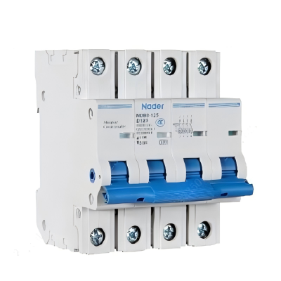
NDB3-125 Series HMCB, Nader
Rated current In (A): 10A, 15A, 16A, 20A, 25A, 30A, 32A, 40A, 50A, 60A, 63A, 70A, 80A, 90A, 100A, 110A, 125A. Rated voltage Ue (V): AC230V/240/400/415V, DC80V/DC125V. Poles: 1P, 1P+N, 2P, 3P, 3P+N, 4P. Breaking capacity Icn: 6kA
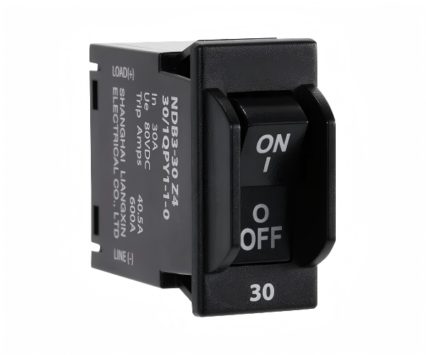
NDB3-30 Series HMCB, Nader
Rated current In (A): 0.1A, 0.2A, 0.3A, 0.4A, 0.5A, 0.6A, 0.7A, 0.75A, 0.8A, 0.9A, 1A, 1.5A, 2A, 2.5A, 3A, 3.5A, 4A, 4.5A, 5A, 5.5A, 6A, 6.5A, 7A, 7.5A, 8A, 8.5A, 9A, 9.5A, 10A, 11A, 12A, 13A, 14A, 15A, 16A, 17A, 18A, 19A, 20A, 21A, 22A, 23A, 24A, 25A, 26A, 27A, 28A, 29A, 30A. Rated voltage Ue (V): AC250V DC80/65V. Poles: 1P, 2P. Breaking capacity Icn: 600A, 1000A
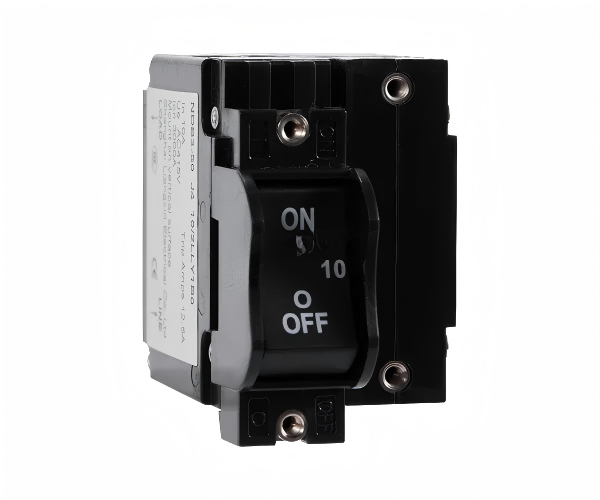
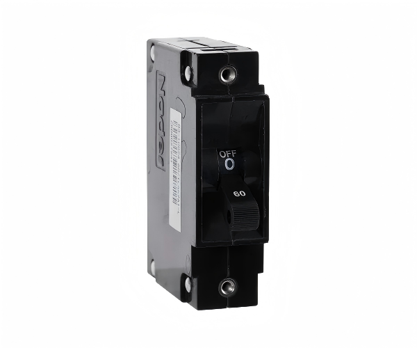
NDB3-50 Series HMCB, Nader
Rated current In (A): 0.5A, 1A, 2A, 2.5A, 3A, 4A, 5A, 6A, 7A, 8A, 9A, 10A, 12A, 15A, 16A, 20A, 24A, 25A, 30A, 32A, 35A, 40A, 45A, 50A. Rated voltage Ue (V): DC80V, AC120/125/240/250/415V. Poles: 1P, 2P, 3P. Breaking capacity Icn: 1000A, 1500A, 2000A, 3000A, 5000A
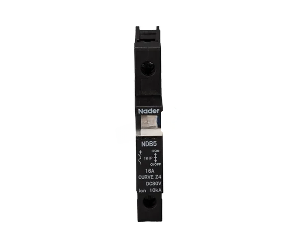
NDB5 Series HMCB, Nader
Rated current In (A): 0.5A, 0.6A, 0.7A, 0.8A, 0.9A, 1A, 1.5A, 2A, 2.5A, 3A, 3.5A, 4A, 4.5A, 5A, 5.5A, 6A, 6.5A, 7A, 7.5A, 8A, 8.5A, 9A 9.5A, 10A, 12A, 15A, 16A, 20A, 24A, 25A, 30A, 32A, 35A, 40A, 45A, 50A, 55A, 60A, 63A, 70A, 80A, 90A, 100A, 105A, 110A, 120A, 125A, 150A. Rated voltage Ue (V): DC80V, AC230/240/250/277/400/415/480V